Media | Articles
How Edelbrock makes its signature aluminum intake manifolds
Edelbrock is one of the best-known speed equipment parts in the business and has been churning out parts in southern California since 1938. That’s when Vic Edelbrock, Sr. first began designing speed parts for the flathead V-8 in his own land-speed racing 1932 Ford.
While the company now produces carburetors, water pumps, and superchargers—along with cylinder heads for engines not supported by many aftermarket parts suppliers—Edelbrock’s cast-aluminum intakes are, without a doubt, its signature product. If you’ve owned a carbureted car powered by an American V-8 engine, odds are you’ve used an Edelbrock intake manifold or thought about installing one.
We were invited to see how Edelbrock turns an ingot of aluminum into an intake manifold. Follow along as we visit two Edelbrock facilities in California to see how it’s done.
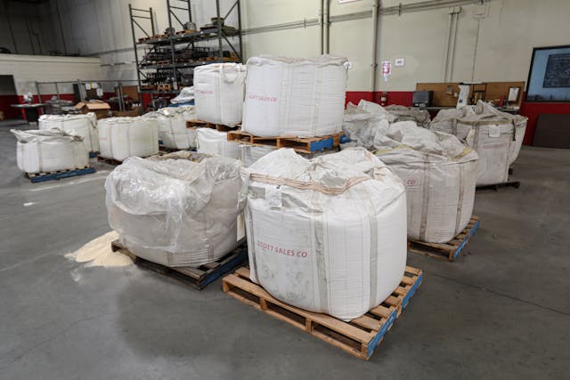
The process starts with pallets upon pallets of aluminum ingots sourced from American suppliers.
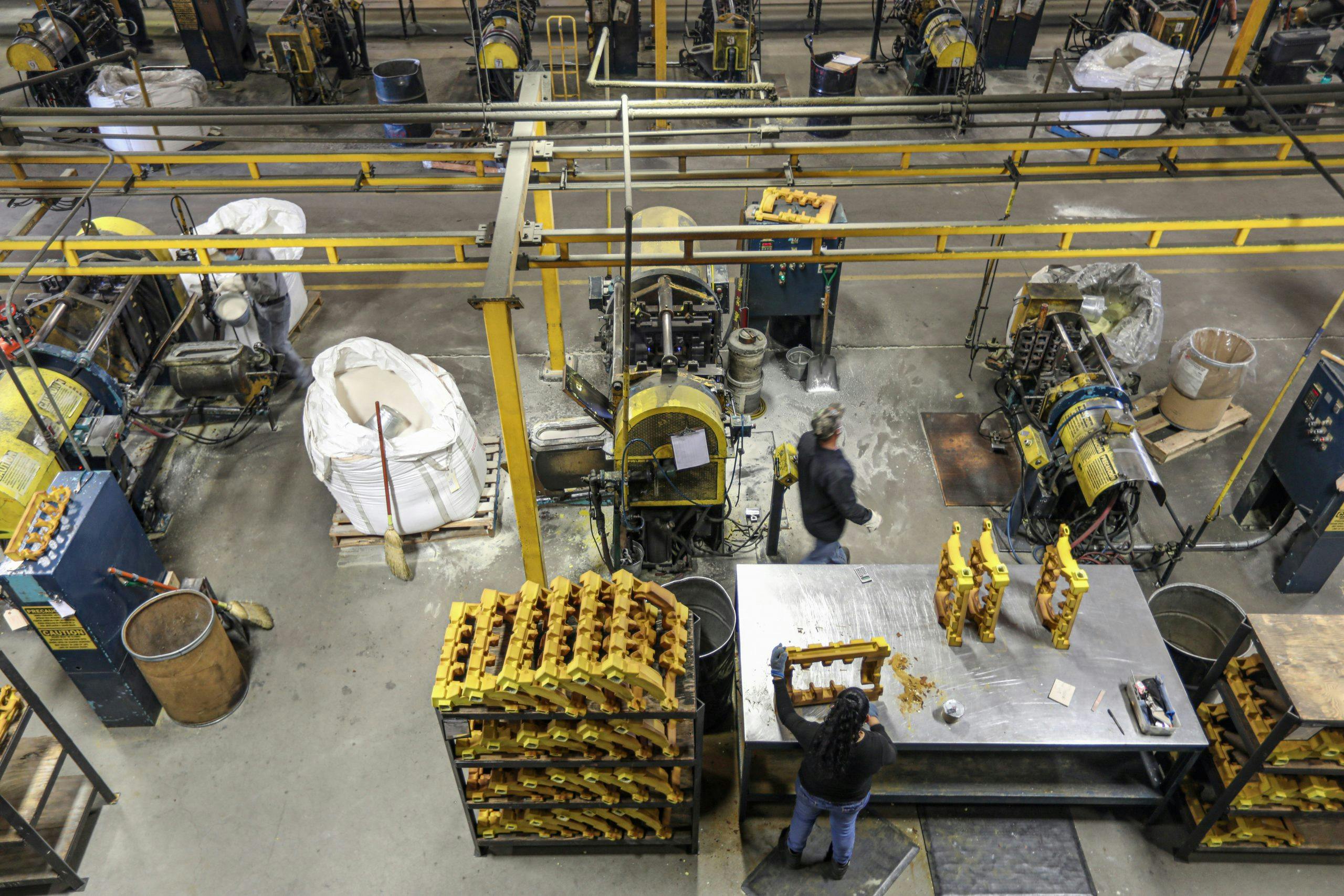
Cores are used to create voids in castings for intake ports, exhaust ports, and water jackets. Edelbrock uses two basic techniques to make its cores. Some cores are formed using a gas catalyst, but the bulk of Edelbrock’s casting involves a shell core process that uses resin-coated sand, which cures with heat.
Marketplace
Buy and sell classics with confidence
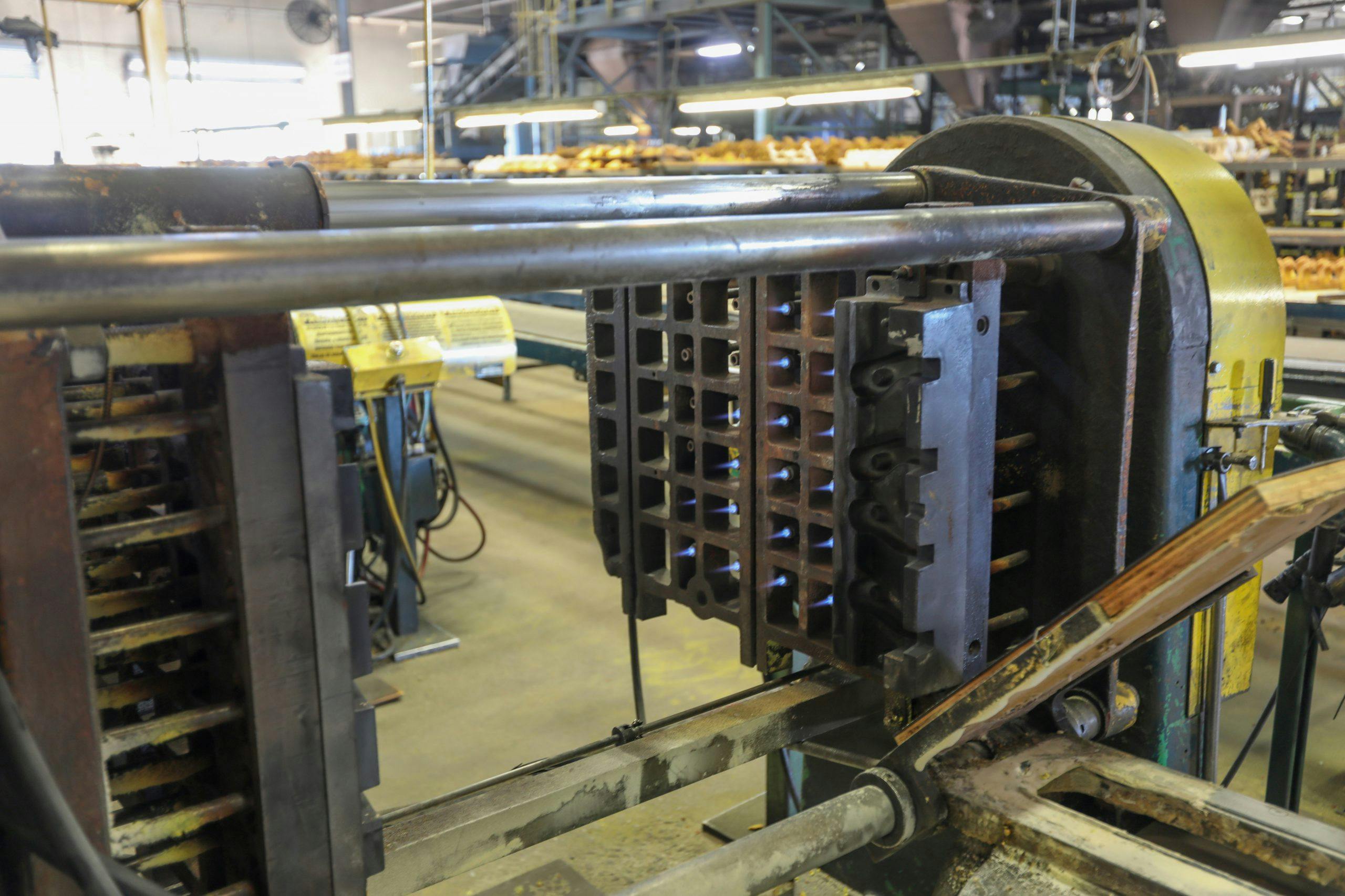
Shell core molds are heated with natural gas and a prescribed volume of sand is blown into the mold before it is rotated to ensure even distribution.
Once removed from the mold, cores are inspected by workers who clean up parting lines and critical surfaces. Note the core mold rotating in the background.
Besides a core, an intake needs a pattern. Edelbrock keeps dozens of manifold design patterns on hand, ready to put into production.
This pattern for a single-plane manifold is cleaned of any residual sand from the last flask before it is sprayed with a release agent.
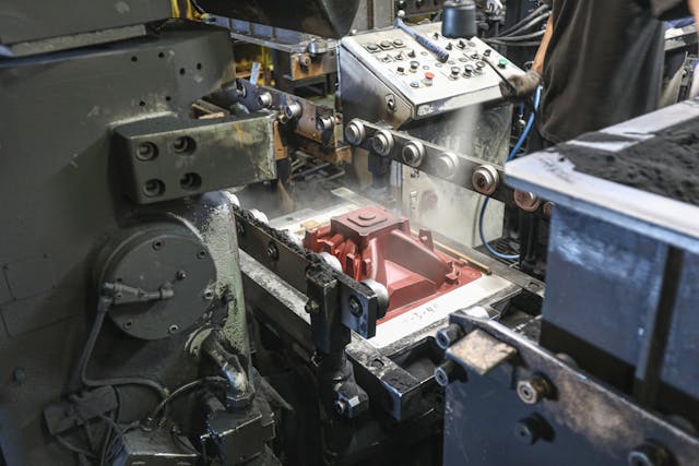
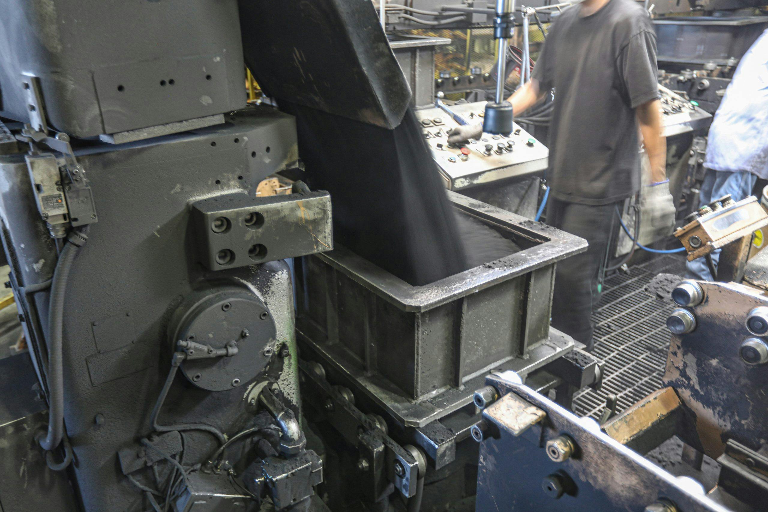
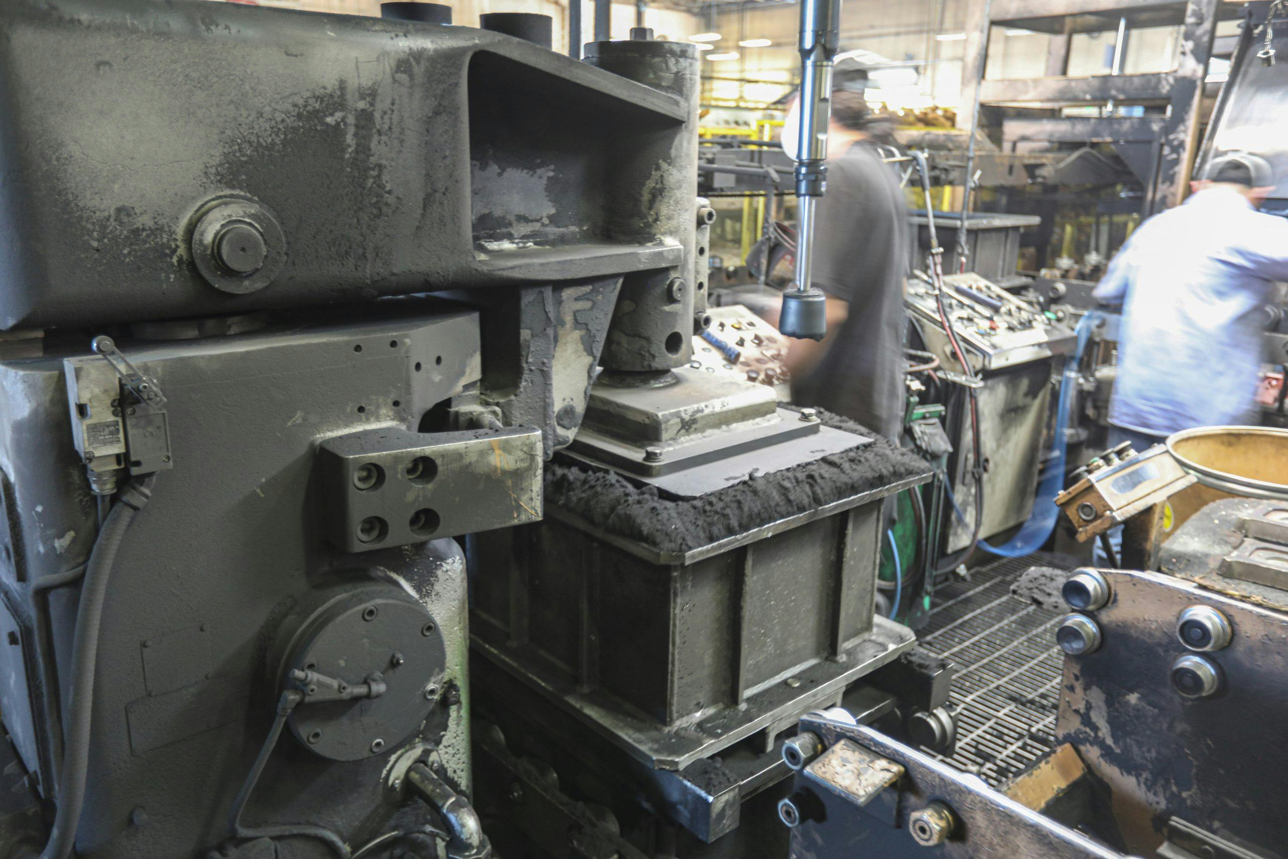
A flask is placed on top of the mold and filled with green casting sand. A plate compacts the sand around the mold. This will be the bottom half of the two-part flask, called the drag.
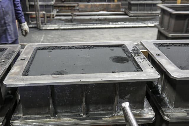
When the drag is flipped over, what’s left is a void in the shape of the manifold. There are also indentations to correctly place the sand cores.
A core for the plenum and runners goes in first. For some manifolds, that’s all that’s necessary. Others manifolds, like this one, require additional cores for the voids between the runners.
A pattern for the bottom of the manifold is used to make the top half of the flask, or cope. When it’s flipped upside down onto the lower flask (the drag), the manifold is ready to be cast.
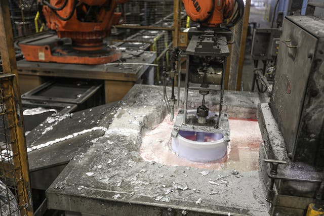
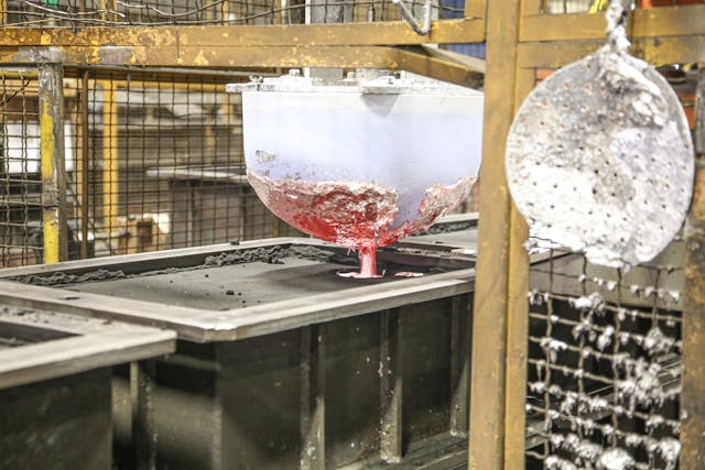
A robotic arm dips the bottom pour ladle into the molten aluminum and retracts a stopper from the center to allow the metal to flow. By avoiding the top of the vat, where residual impurities may still remain, this method helps to ensure the material remains clean.
Like the core molds, the furnace that melts the aluminum is heated with natural gas.
Once the ladle is positioned over the sprue, the stopper rod is pulled up and metal flows in.
Freshly-cast parts are removed from their flasks after just a few minutes. A robotic arm lifts the flasks and rotates it 180 degrees before a ram presses the part and the sand into a hopper. The flasks then return for another fill and workers use a pneumatic lifting tool to grab the hot parts and set them in a bin. They’ll be allowed to fully cool overnight.
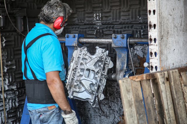
Once cooled, parts head to a pneumatic A-frame core removal machine that shakes the part to break up the cores within them, allowing the sand to drain. This is the loudest operation at the casting facility, by far.
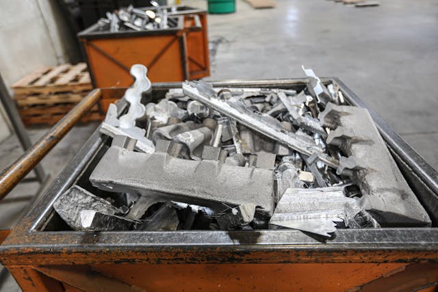
Workers use saws to cut the gates, sprues, and risers from each casting. The aluminum is all recycled on-site.
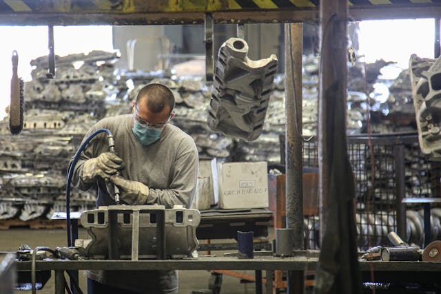
Next, parts move via an overhead conveyer to a series of workers who touch up the saw cuts and blend them in using die grinders.
Some manifolds are made using an alloy that’s ready to use once cast. Other, high-performance manifolds—and some cylinder heads—are cast using A356 aluminum and require a heat-treat process to bring them to T6 hardness. These ovens (pictured below) ferry the parts along through multiple heating and cooling cycles that result in a much harder part that can readily sustain boost and cylinder pressures.
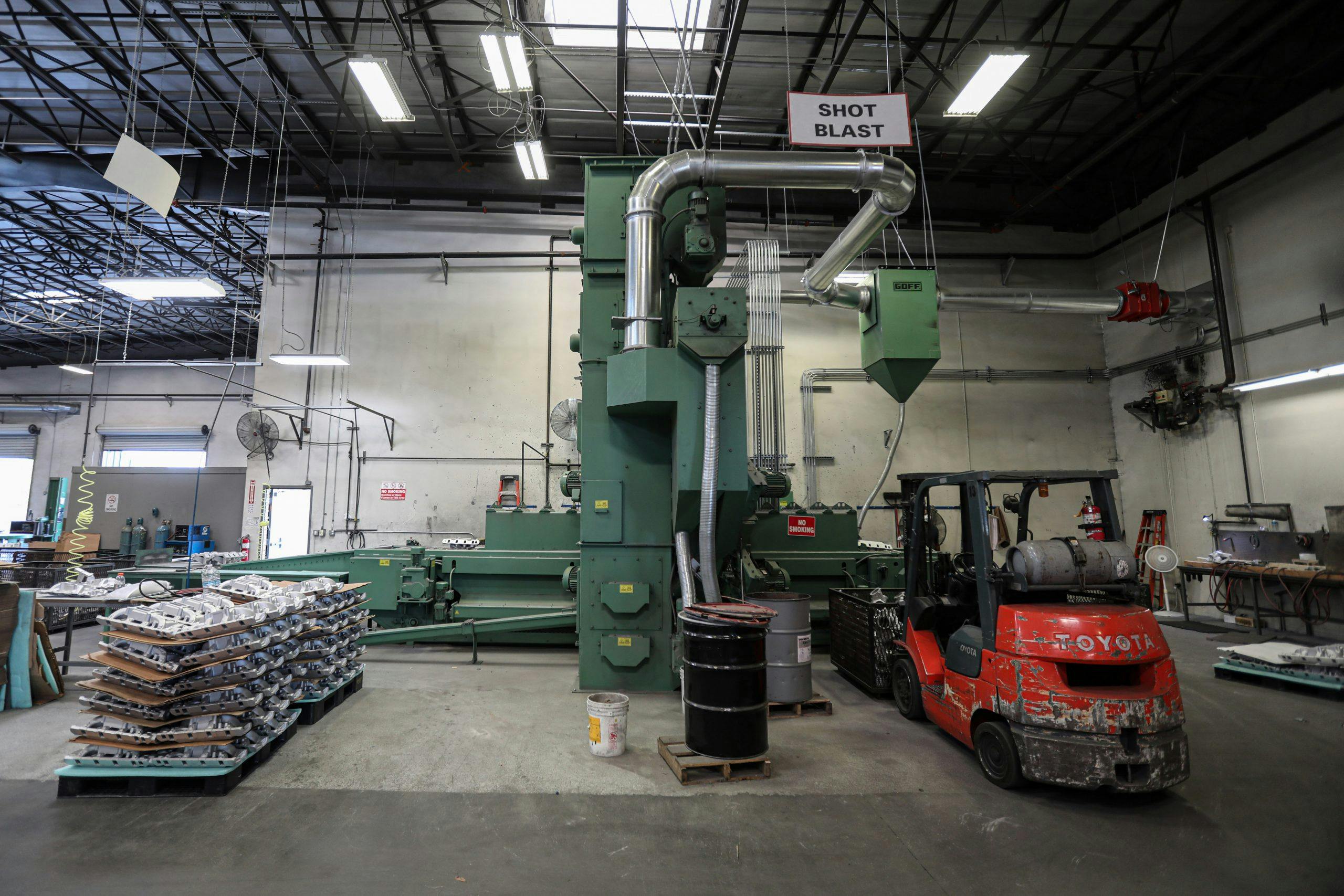
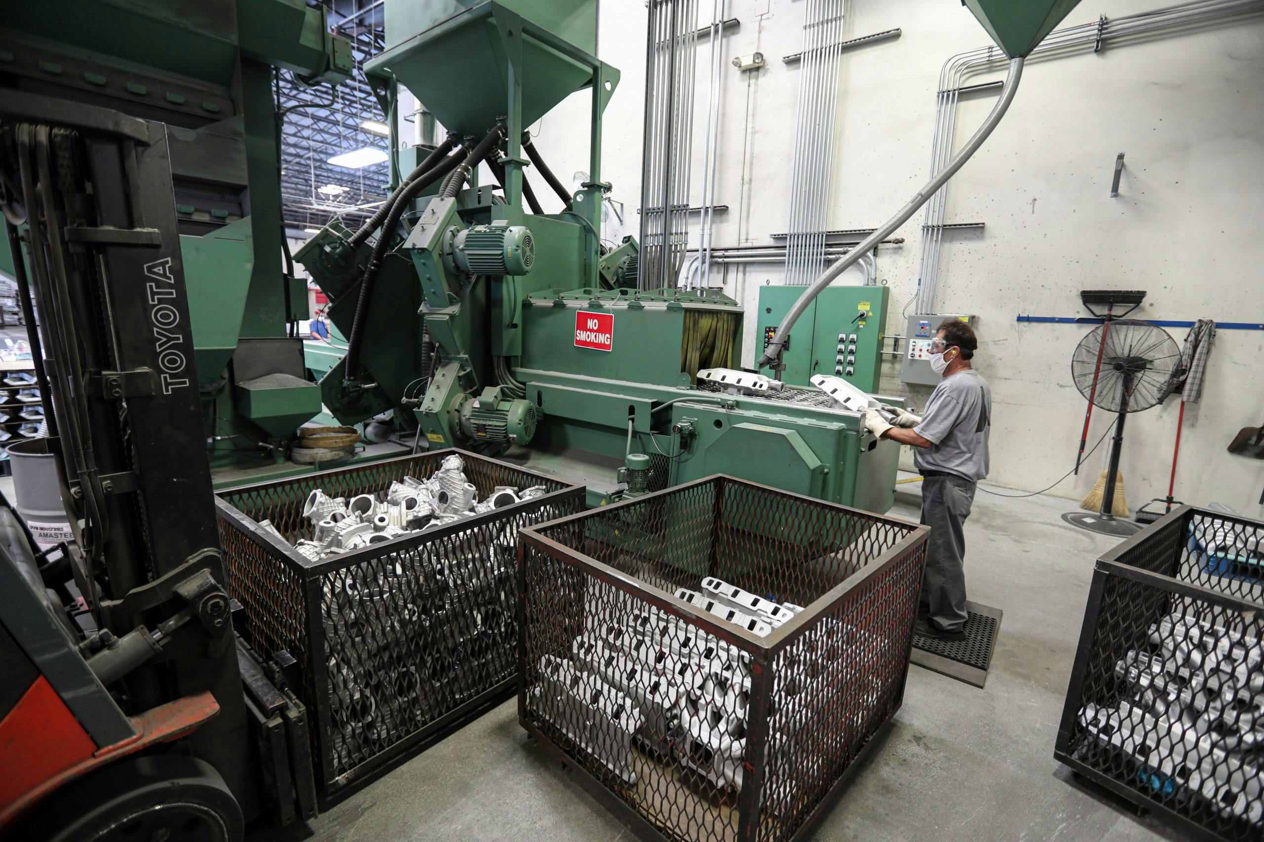
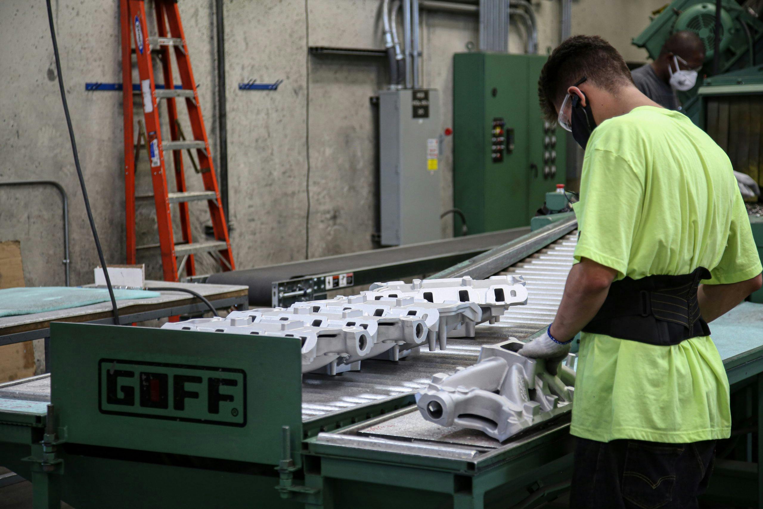
Next, parts move through a shot-blast cabinet where they travel on a belt at six feet per minute and are bombarded with steel shot from eight different angles. When they come out, their surfaces are clean and peened smooth, but there’s still plenty of work to be done.
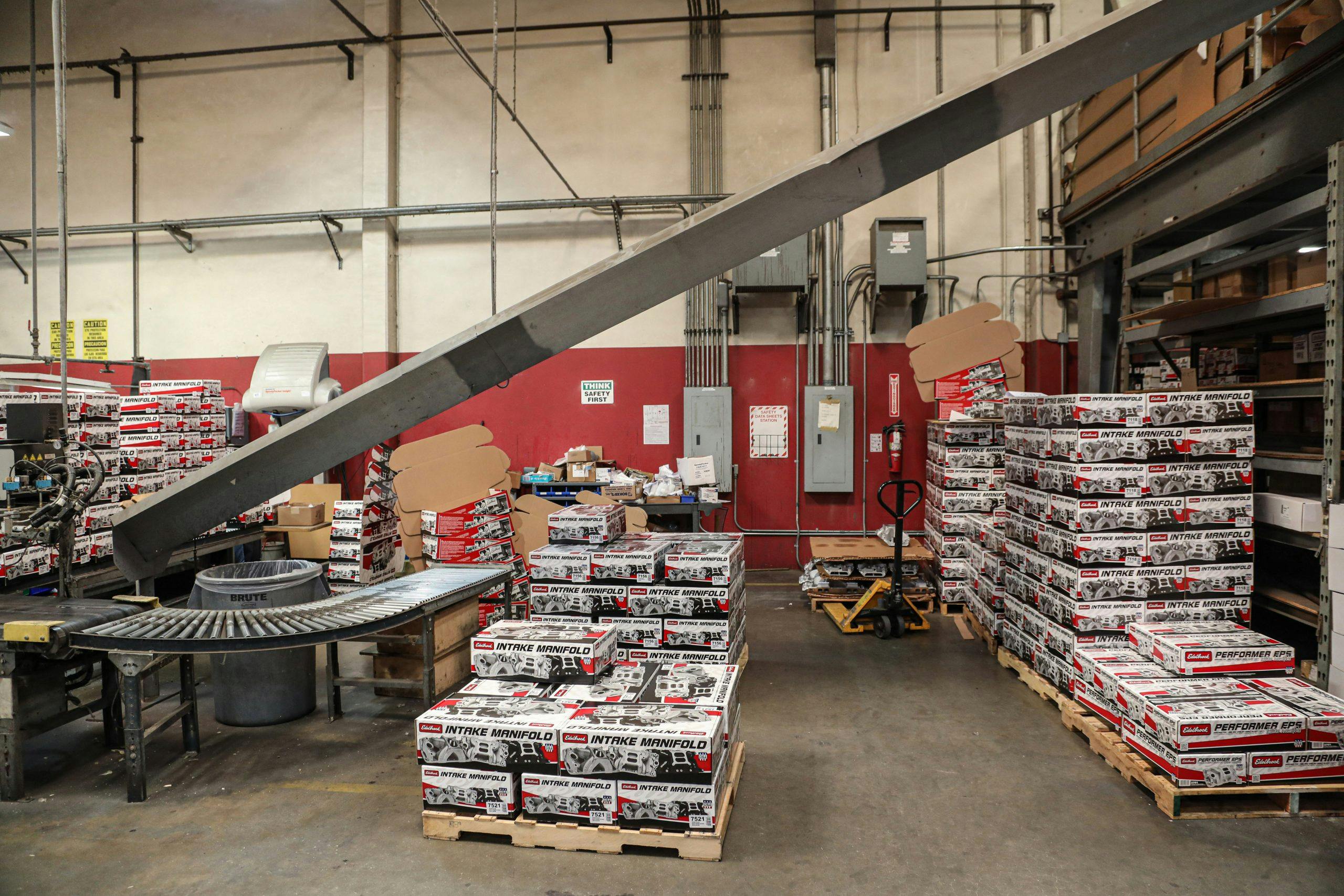
Final machining and packaging takes place at Edelbrock’s facility in Torrance, California. Parts are placed on pallets and make trips to the location every day.
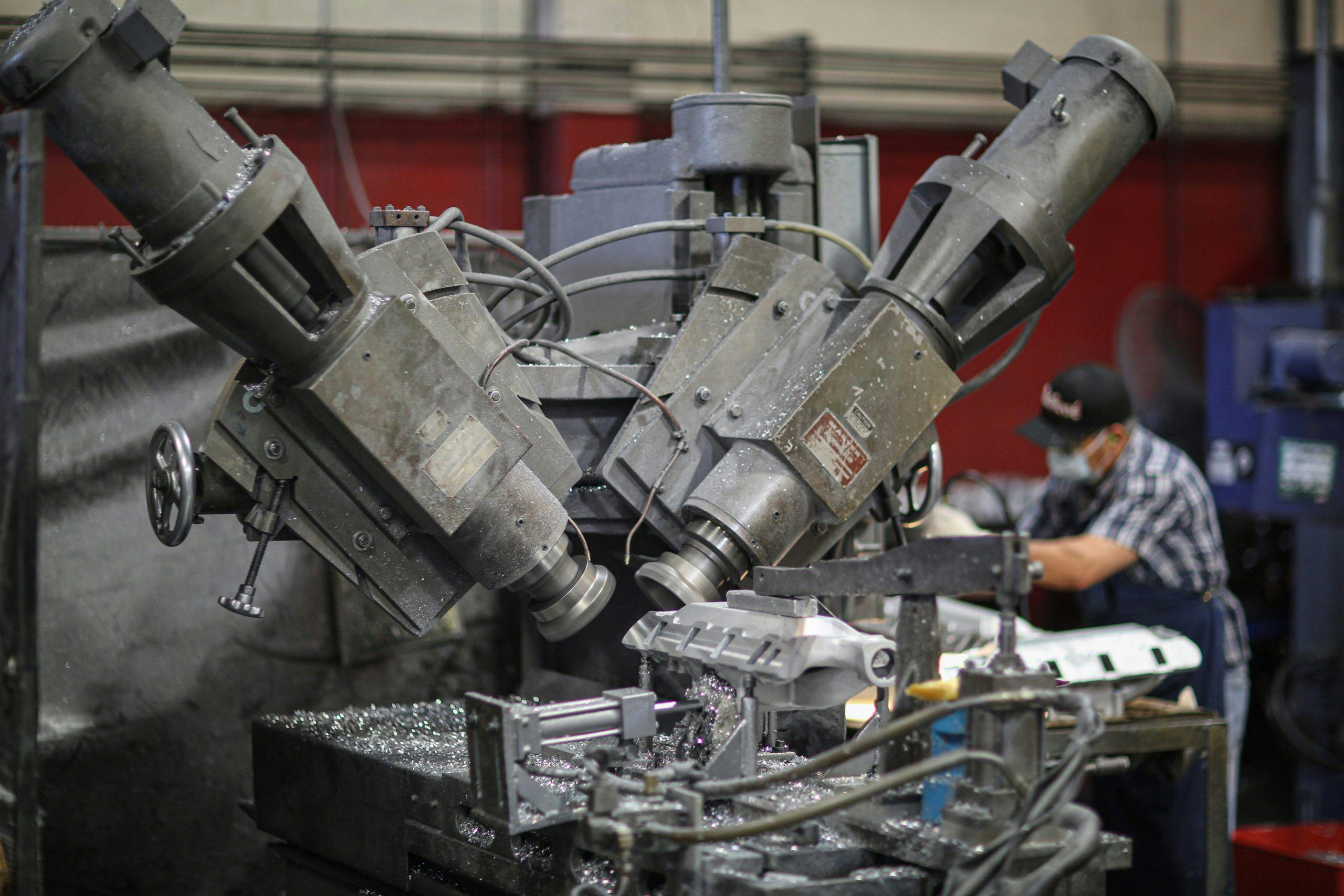
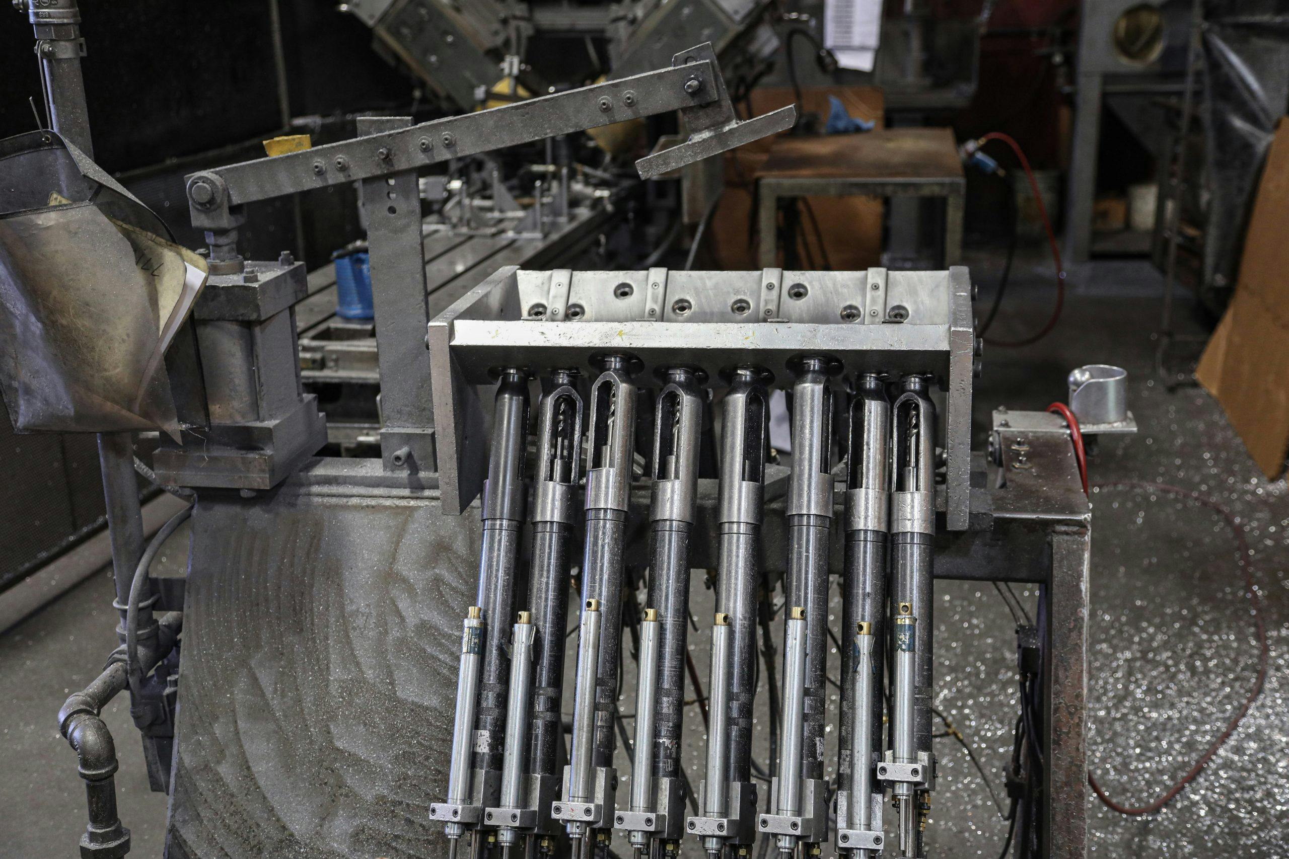
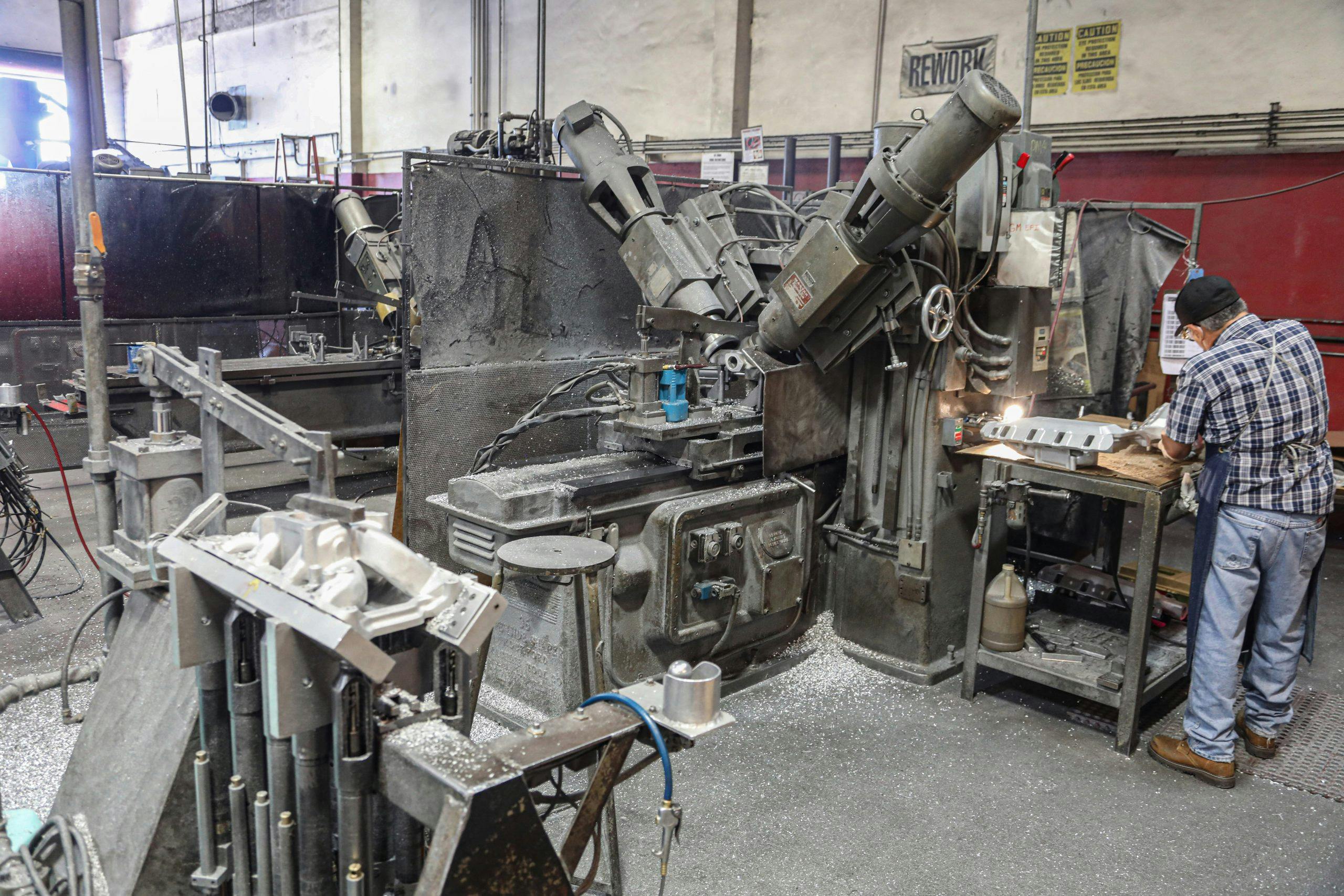
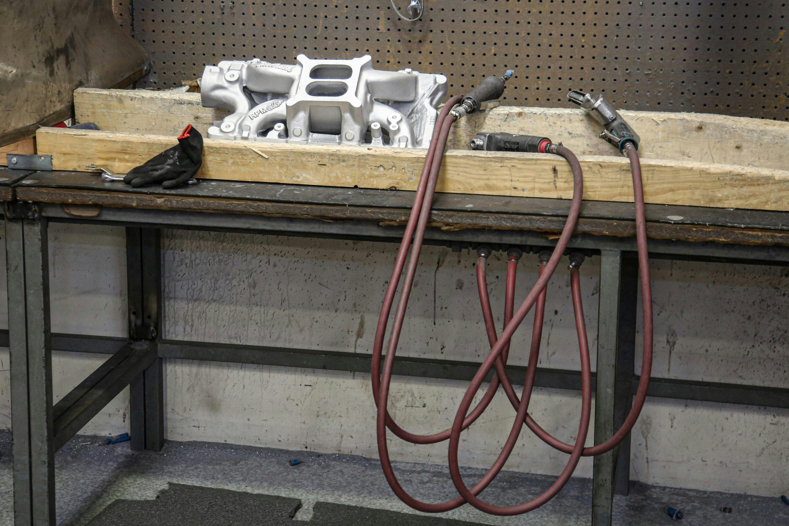
The first machining process cuts the gasket surface that mounts to the cylinder heads. A mill fly-cuts both surfaces simultaneously and then a worker cleans the burrs and removes any sharp edges left by the cutters. Then the manifold is moved to a fixture that uses pneumatic drills to simultaneously bore all the mounting holes from the bottom up.
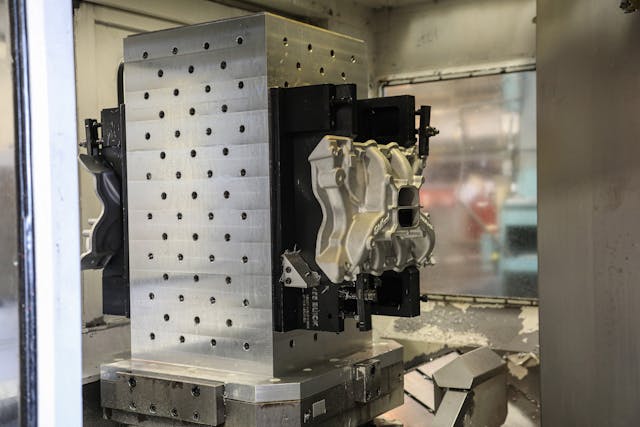
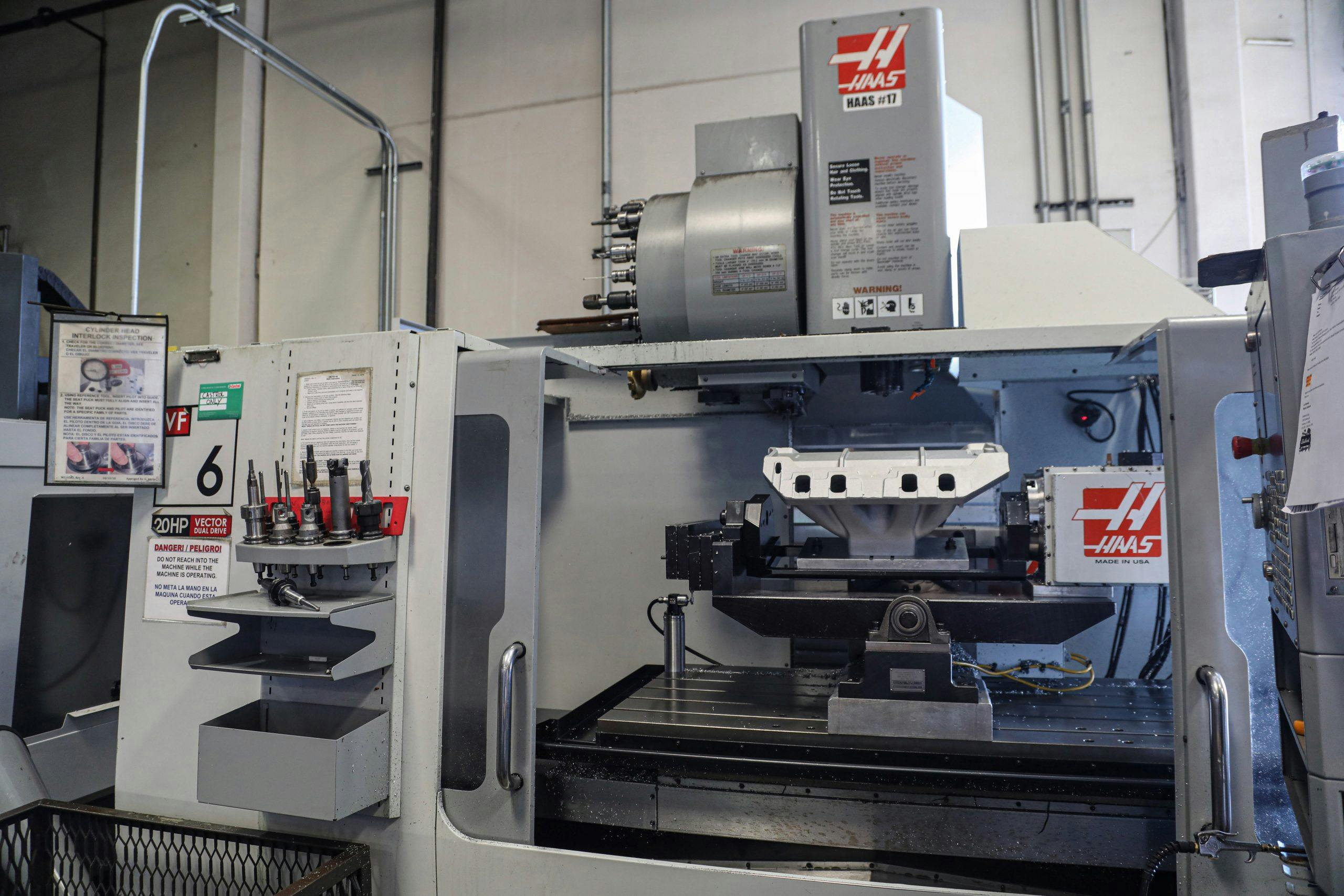
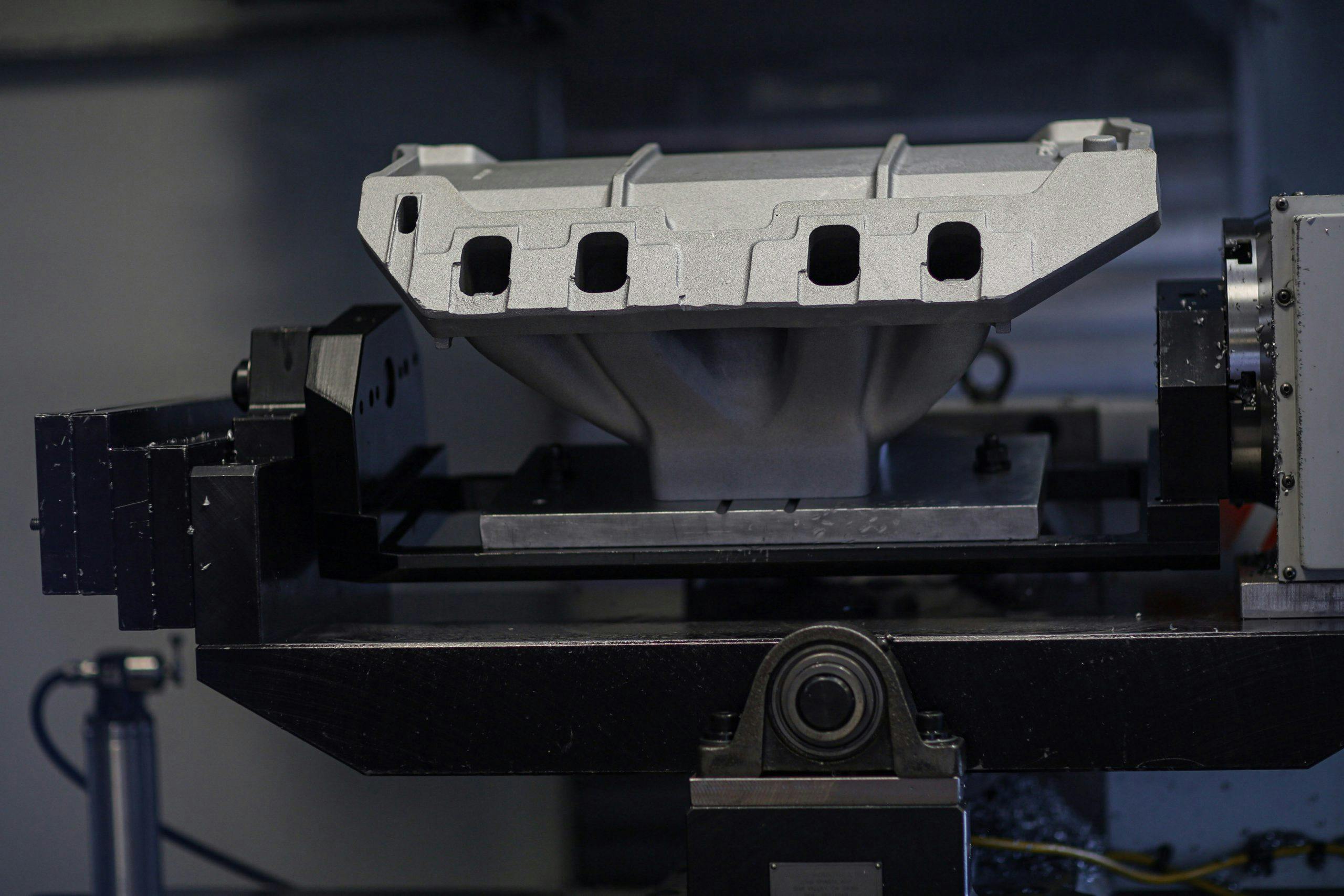
Many of the machining processes have been moved to CNC machines—like this one, which is getting ready to mill the carb mounting flange on this intake.
Edelbrock also offers high-end race manifolds that are CNC port-matched to their cylinder heads.
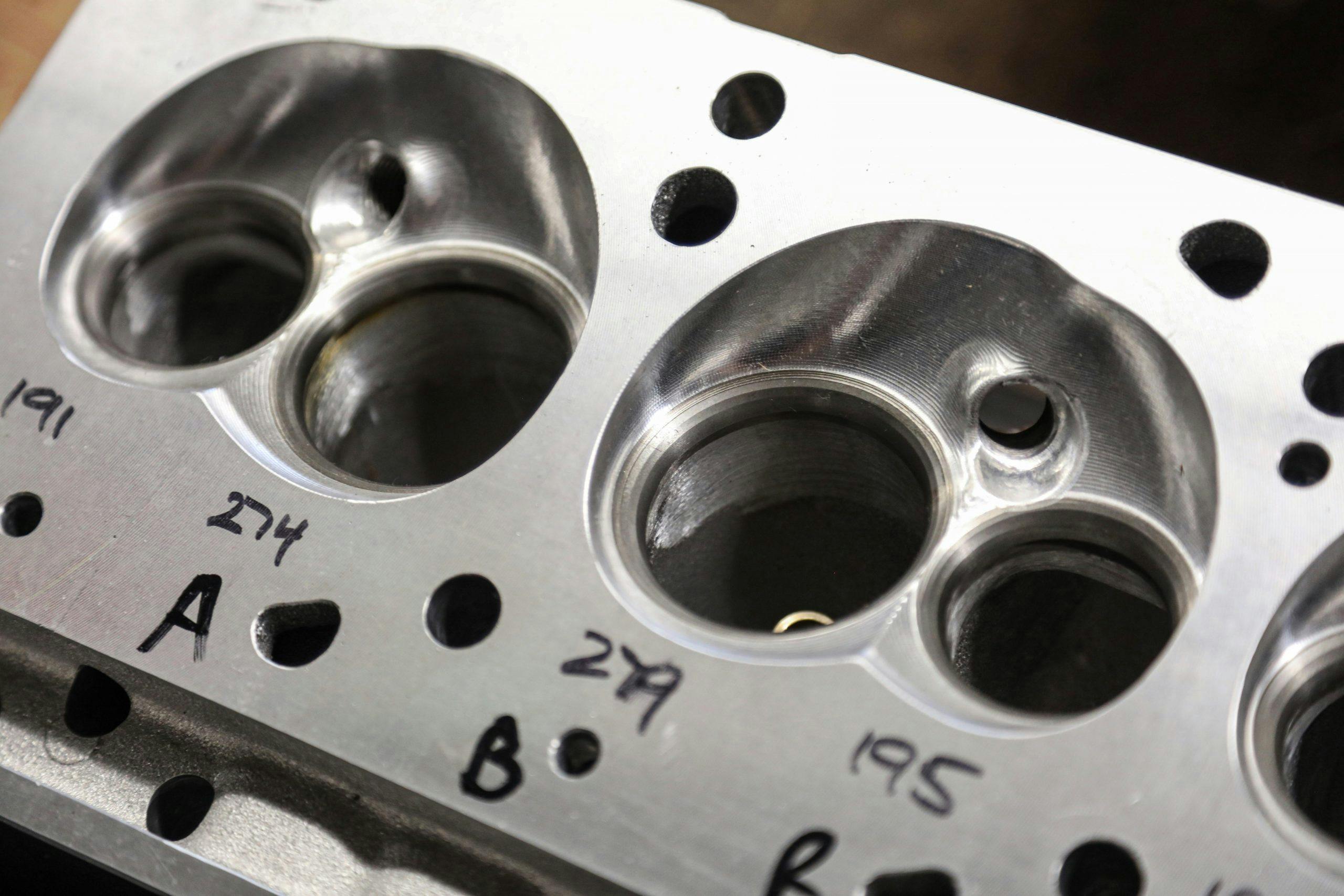
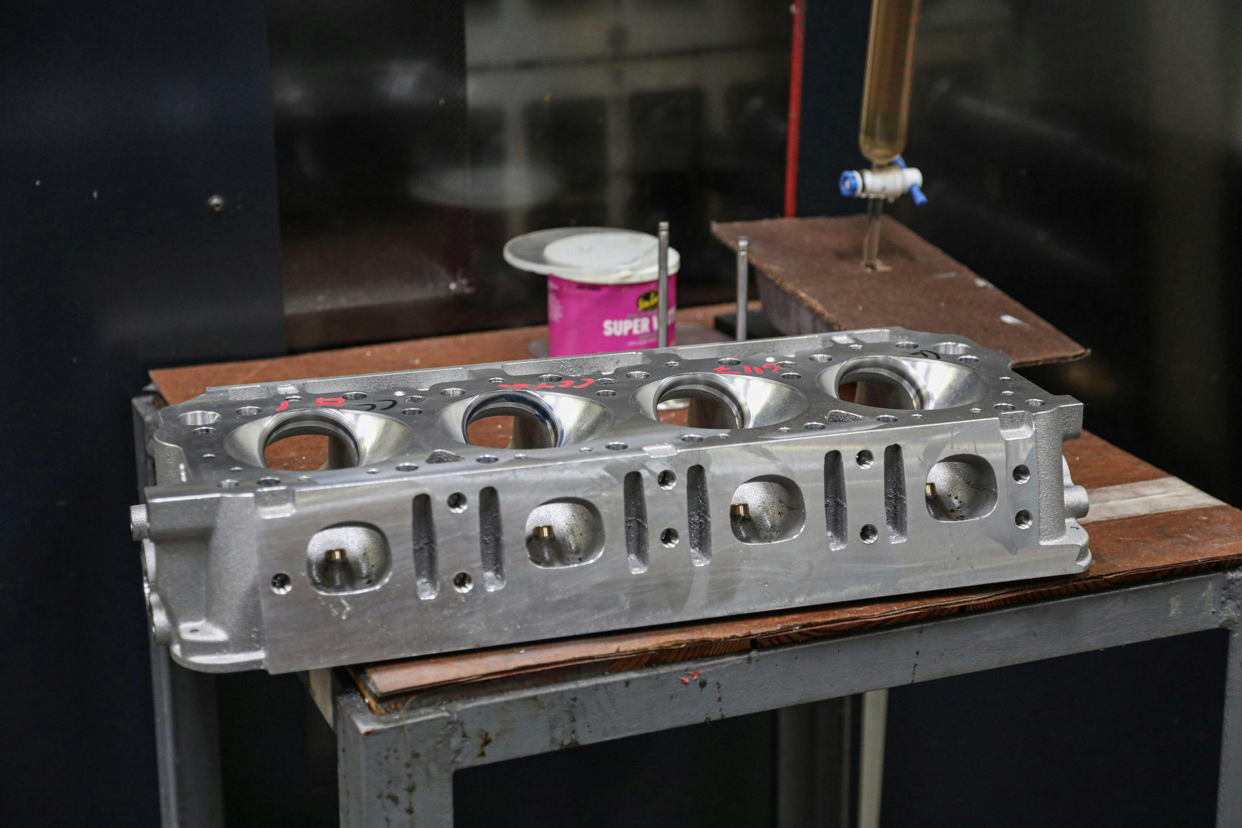
Manifolds are inspected at several steps along the process and get hands-on touches to remove burrs and smooth sharp edges. Cylinder heads undergo even more scrutiny. Parts are periodically plucked off the line so workers can test flow and check combustion chamber volume.
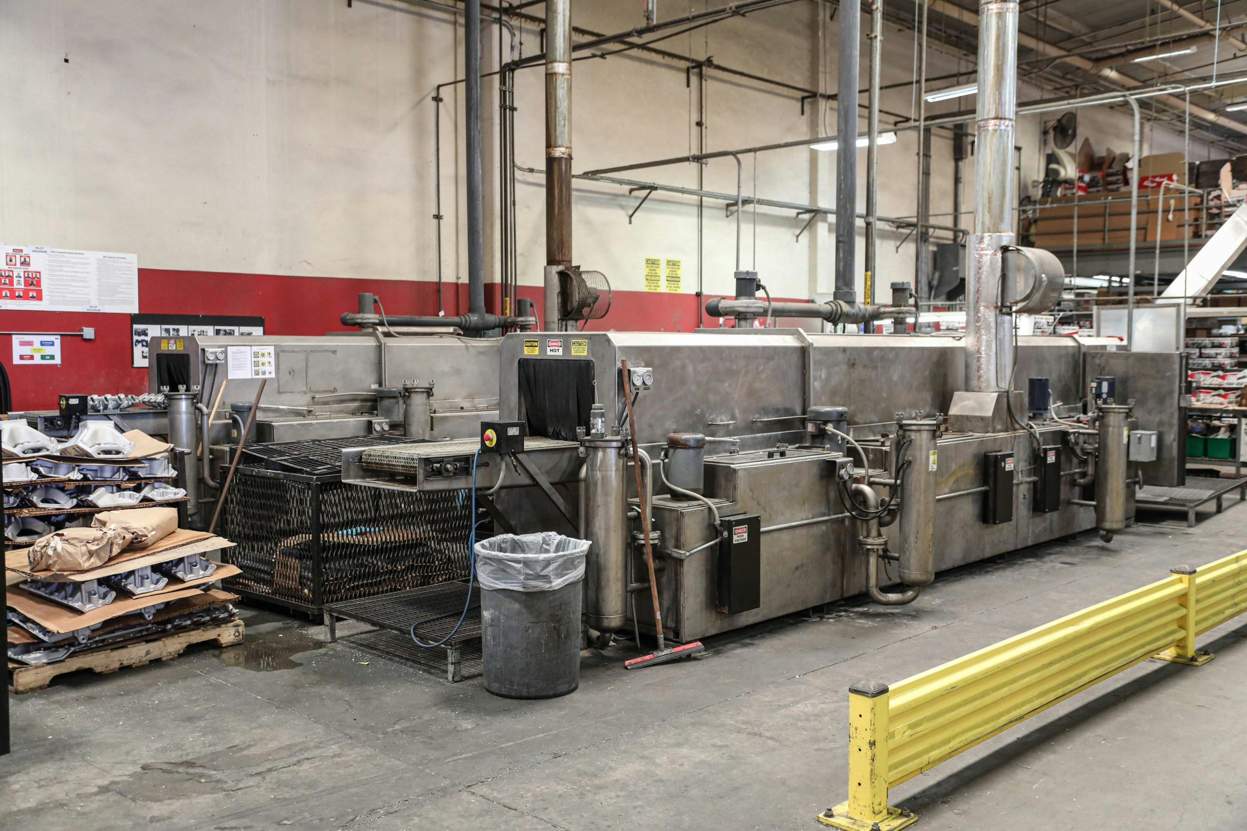
After inspection, manifolds are ready for packaging. They get wrapped and placed into boxes at one end of this machine and emerge sealed at the other end, ready to be shipped to parts warehouses and your local speed shop.


